
Concealed within humming server rooms and above drop ceilings, there exists a critical weakness that conventional network diagnostics often fail to detect. Many organizations mistakenly believe that as long as link lights are green and ping tests succeed, their wired infrastructure is in good shape. Yet, beneath these surface indicators, hidden problems may persist compromising performance, compliance, and safety.
During a recent survey of a 16,000-square-foot wired facility at a major U.S. distribution center, this false sense of security was quickly dispelled. The assessment revealed deep-rooted cabling issues that, if ignored, could have resulted in significant annual downtime. The findings went beyond a single faulty cable or overloaded switch instead, they revealed how widespread neglect of structured cabling standards can create hidden, high-risk vulnerabilities throughout enterprise networks.
Key Findings Included:
- Performance bottlenecks, with degraded throughput despite “10Gbps-capable” hardware
- Compliance violations, including TIA-568.2-D and NEC 300.11 lapses
- Safety hazards, such as overheated PoE++ runs and unterminated cable shielding
What looked like a reliable network was actually hampered by signal loss, deteriorating cables, and poor distance planning. Addressing these issues required more than simply replacing wires, it demanded a forward-thinking installation approach based on comprehensive survey insights.
The outcome was a durable, high-performing infrastructure designed for sustained growth, dependable operations, and full compliance. If your facility depends only on software checks for network health, it’s time to examine the physical layer before minor problems escalate into major disruptions.
Key Installation Objectives:
- Upgrade outdated copper cabling with shielded CAT6A to support APs and edge devices
- Introduce a new IDF to resolve excessive cable lengths
- Use fiber backbone to bridge MDF to IDF across warehouse wings
- Deploy a number of APs for full indoor/outdoor coverage with external antennas in high-rack zones
- Mount hardware to meet environmental and access constraints (e.g., 30' ceilings)
- Ensure all cabling and AP placements comply with standards to support 10Gbps uplinks and optimal Wi-Fi performance.
Structured Cabling: Replacing the Network’s Lifeline
A network is only as strong as its physical layer. The existing infrastructure in this facility included legacy copper cabling and ad-hoc pathways that had evolved with the space, but not with its technology needs. The new approach focused on predictability, labeling, and long-term maintenance.
Horizontal Cabling Strategy :
- New CAT6A cables were installed to support APs and edge devices
- Previously installed cables were reused after thorough inspection for shielding and continuity
- Cables were routed with careful attention to bend radius, separation from power lines, and ceiling space congestion
Routing and Mounting :
- Cable trays and J-hooks were installed to provide permanent cable pathways
- In some areas, existing penetrations were fire-sealed and reused; in others, new grommets and sleeves were installed for code compliance
- Cable slack loops were introduced at endpoints to simplify future changes
Labeling and Documentation :
- Cables were labeled at both ends, tagged with drop numbers, length records, and floor plan references
- All labeling followed TIA-606 standards and was recorded in an installation matrix handed over to the client
- Patch panels were color-coded based on destination zone (e.g., docks, offices, racking)
MDF/IDF Buildout: A Backbone Reinforced
MDF Room Upgrades :
- Redundant switch stacks were reorganized to distribute AP loads evenly across PoE+ ports
- Patch panels were consolidated, freeing up 6U of rack space
- A UPS unit was added and the existing PDU reorganized to prevent brownouts
- All open copper and fiber ports were labeled, dressed, and documented
IDF Deployment :
- A new IDF cabinet was mounted near the shipping dock to reduce cable distances to far-end APs
- Single-mode fiber was pulled through conduit over a 350-foot span
- Slimline rack was grounded to a new busbar with insulated bonding braid
- Dual fiber links were terminated to support redundancy and failover paths

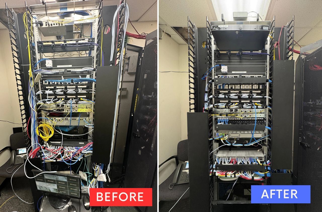
Cluttered cabling and unmanaged patch panels were replaced with a clean, organized rack for improved performance and serviceability.
Wireless AP Installation: Ceiling to Steel Truss
Office Zones (1st and 2nd Floor) :
- APs installed flush with acoustic tiles to preserve aesthetics
- Internal antennas provided clean coverage in meeting rooms and corridors
- Mounted at 8 feet, connected to shielded Cat6A for PoE+ delivery
Warehouse Zones :
- APs mounted on I-beams at 20–25 feet, ensuring vertical and horizontal coverage in high-bay racking aisles
- Patch and omni-directional antennas selected based on propagation patterns validated in the site survey
- Cable runs were kept under 295 feet with new IDF acting as mid-span link
Loading Dock :
- External antennas mounted just inside the building envelope to minimize weather exposure
- Mounts reinforced to withstand air pressure changes and vibrations from freight movement
- Antenna alignment was verified using handheld directional testers post-mount
Testing and Post-Install Validation
Once physical installation was complete, a multi-layered testing phase began:
Copper Testing :
- Every new CAT6A cable was tested using a certified cable analyzer
- Tests included length, wire map, NEXT, PSNEXT, ACR-F, and Return Loss
- All links passed at 10GBase-T with margin, and reports were handed off in digital format
Fiber Validation :
- OTDR testing confirmed signal integrity across the 350-foot backbone
- Insertion loss and reflectance were within limits for SM fiber
- LC connectors were polished and cleaned before final patching
Wireless Heatmap Validation :
- A post-install wireless survey was conducted to validate AP placement
- Overlap exceeded 20% across all critical areas
- Roaming was tested using tablets and handheld scanners
- No coverage dead zones were identified, and signal strength averaged above -62 dBm

Simulated signal strength maps show consistent 5GHz and 2.4GHz coverage, with strategic AP placement ensuring optimal warehouse RSSI.
Installation Challenges & Resolutions
Long Distance Limitations:
- APs originally routed to MDF would have exceeded 300 feet
- A new IDF cabinet was installed at a midway point, reducing length to within spec
Cable Reuse Evaluation :
- Existing cables were originally marked for reuse and were retested
- Time-domain reflectometry revealed minor shield degradation in one replaced proactively
Environmental Considerations :
- Several APs near the loading dock had to be secured against vibration and dust
- Industrial Velcro and custom-mount hardware were introduced to address the issue
Final Results
The results of this upgrade were both quantitative and qualitative:
- Latency on handheld devices dropped from 120 ms to under 3 ms
- Signal loss from edge APs dropped by 20–25 dB after switching from legacy runs
- Client staff reported zero roaming interruptions during real-time pick-pack operations
- UPS-backed infrastructure ensured uptime during a simulated power drop test
Lessons from the Field
-
Do not rely on ping tests to assess cable health certify everything
-
Leave extra rack space and spare ports it’s never wasted
-
Drop ceilings make AP install easy but verify tile load ratings before mounting
-
Label in the field, not just in the plan field accuracy saves hours later
Please get in touch with the experts at Orion US today.

Image Source: Canva